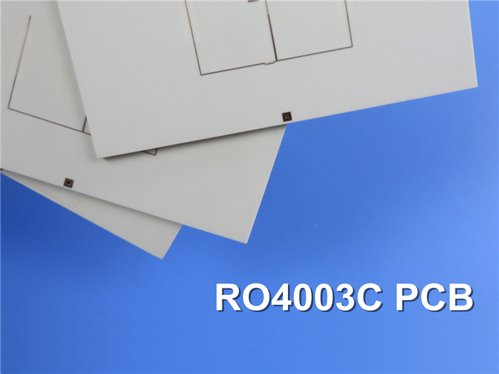
Rogers 4003 60mil 1.524mm Circuit Board: RO4003C High-Frequency PCB for WLAN Applications
(Printed Circuit Boards (PCBs) are tailored products; the images and specifications provided are for reference only.)
Overview of RO4003C
Today, we are excited to introduce the high-frequency PCB constructed with RO4003C laminates.
RO4003C hydrocarbon ceramic laminates are engineered to deliver exceptional high-frequency performance while ensuring cost-effective circuit fabrication. When operational frequencies reach 500 MHz and above, the selection of suitable laminates for designers becomes significantly limited. The RO4003C material possesses essential properties that cater to the needs of RF microwave circuit designers, matching networks, and controlled impedance transmission lines. Its low dielectric loss enables the use of RO4003C in various applications where conventional circuit board materials fall short due to higher operating frequencies.
One standout feature of RO4003C is its low temperature coefficient of dielectric constant, making it one of the best choices among circuit board materials. This laminate maintains a stable dielectric constant over a wide frequency range. Additionally, the thermal coefficient of expansion (CTE) of RO4003C offers crucial advantages for PCB designers. Its expansion coefficient closely matches that of copper, resulting in excellent dimensional stability—a vital attribute for constructing mixed dielectric multilayer boards. The low Z-axis CTE of RO4003C ensures reliable quality in plated through-holes, even under severe thermal shock conditions. With a glass transition temperature (Tg) exceeding 280°C, RO4003C's expansion characteristics remain consistent throughout the entire range of PCB processing temperatures.
PCB Specifications
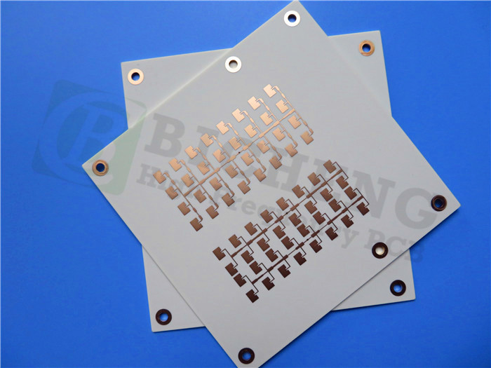
Rogers 60mil 1.524mm RO4003C High Frequency PCB Double Sided RF PCB for WLAN |
|
PCB SIZE |
84 x 78mm=1PCS |
BOARD TYPE |
RF PCB, Microwave PCB |
Number of Layers |
Double sided PCB |
Surface Mount Components |
YES |
Through Hole Components |
YES |
LAYER STACKUP |
copper ------- 35um(1oz)+PLATE |
RO4003C 60mil |
|
copper ------- 35um(1oz)+PLATE |
|
TECHNOLOGY |
|
Minimum Trace and Space: |
10mil/12mil |
Minimum / Maximum Holes: |
0.3/2.3mm |
Number of Different Holes: |
4 |
Number of Drill Holes: |
155 |
Number of Milled Slots: |
0 |
Number of Internal Cutouts: |
0 |
Impedance Control |
NO |
BOARD MATERIAL |
|
Glass Epoxy: |
RO4003C 60mil, Tg 288℃ |
Final foil external: |
1.5oz |
Final foil internal: |
0oz |
Final height of PCB: |
1.6mm ±0.16 |
PLATING AND COATING |
|
Surface Finish |
Electroless nickel over Immersion Gold (ENIG)( 2 µ" over 100 µ" nickel) |
Solder Mask Apply To: |
no Solder mask reqruied |
Solder Mask Color: |
no solder mask required |
Solder Mask Type: |
no solder mask reqruied |
CONTOUR/CUTTING |
Routing |
MARKING |
|
Side of Component Legend |
no silkscreen required |
Colour of Component Legend |
no silkscreen required |
Manufacturer Name or Logo: |
no silkscreen required |
VIA |
Plated Through Hole(PTH) |
FLAMIBILITY RATING |
N/A |
DIMENSION TOLERANCE |
|
Outline dimension: |
0.0059" (0.15mm) |
Board plating: |
0.0030" (0.076mm) |
Drill tolerance: |
0.002" (0.05mm) |
TEST |
100% Electrical Test prior shipment |
TYPE OF ARTWORK TO BE SUPPLIED |
email file, Gerber RS-274-X, PCBDOC etc |
SERVICE AREA |
Worldwide, Globally. |
Typical Applications
.Automotive Radar and Sensors
.Cellular Base Station Antennas
.Direct Broadcast Satellites
.Low Noise Block Converters
.Power Amplifiers
.RFID Technology
Data Sheet for Rogers 4003C (RO4003C)
RO4003C Typical Value |
|||||
Property |
RO4003C |
Direction |
Units |
Condition |
Test Method |
Dielectric Constant,εProcess |
3.38±0.05 |
Z |
|
10 GHz/23℃ |
IPC-TM-650 2.5.5.5 Clamped Stripline |
Dielectric Constant,εDesign |
3.55 |
Z |
|
8 to 40 GHz |
Differential Phase Length Method |
Dissipation Factortan,δ |
0.0027 |
Z |
|
10 GHz/23℃ |
IPC-TM-650 2.5.5.5 |
Thermal Coefficient of ε |
+40 |
Z |
ppm/℃ |
-50℃to 150℃ |
IPC-TM-650 2.5.5.5 |
Volume Resistivity |
1.7 x 10¹⁰ |
|
MΩ.cm |
COND A |
IPC-TM-650 2.5.17.1 |
Surface Resistivity |
4.2 x 10⁹ |
|
MΩ |
COND A |
IPC-TM-650 2.5.17.1 |
Electrical Strength |
31.2(780) |
Z |
Kv/mm(v/mil) |
0.51mm(0.020") |
IPC-TM-650 2.5.6.2 |
Tensile Modulus |
19,650(2,850) |
X |
MPa(ksi) |
RT |
ASTM D 638 |
Tensile Strength |
139(20.2) |
X |
MPa(ksi) |
RT |
ASTM D 638 |
Flexural Strength |
276 |
|
MPa |
|
IPC-TM-650 2.4.4 |
Dimensional Stability |
<0.3 |
X,Y |
mm/m |
after etch+E2/150℃ |
IPC-TM-650 2.4.39A |
Coefficient of Thermal Expansion |
11 |
X |
ppm/℃ |
-55℃to288℃ |
IPC-TM-650 2.4.41 |
Tg |
>280 |
|
℃ TMA |
A |
IPC-TM-650 2.4.24.3 |
Td |
425 |
|
℃ TGA |
|
ASTM D 3850 |
Thermal Conductivity |
0.71 |
|
W/M/oK |
80℃ |
ASTM C518 |
Moisture Absorption |
0.06 |
|
% |
48hrs immersion 0.060" |
ASTM D 570 |
Density |
1.79 |
|
gm/cm3 |
23℃ |
ASTM D 792 |
Copper Peel Stength |
1.05 |
|
N/mm |
after solder float 1 oz. |
IPC-TM-650 2.4.8 |
Flammability |
N/A |
|
|
|
UL 94 |
Lead-free Process Compatible |
Yes |
|
|
|
|